Exercise 4 - Connectors
In this exercise you will use the CAD tools to create a square and a circle and then connect/trim the profiles to create the geometry shown below.
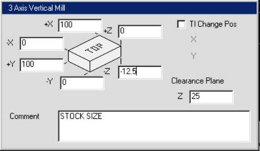
Create a new file named CONNECTORS. Set the machine type to 3 axis vertical mill and the units to mm. Enter the values below for the stock size.
Select the Geometry icon from the Top Level Palette.

The
Geometry Palette will appear.
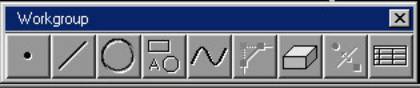
Select
the Shapes icon.

The
Shapes Palette will appear.
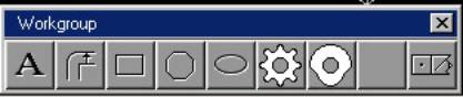
Select
the Box icon from the Shapes Palette.

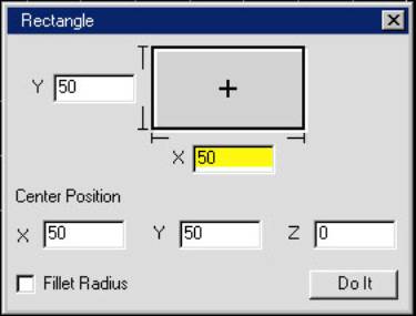
Enter
the values below to create a square.
Click on Do It.
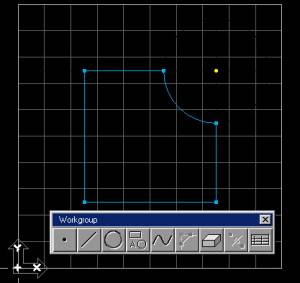
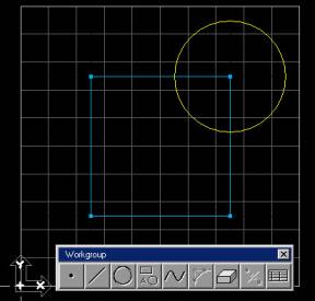
Close the Rectangle dialog box. Your screen should look like this.
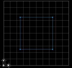
Notice
that the endpoints of the lines of the square have blue points. These are connectors. Connectors allow the shape to be selected as
one continuous entity later on in the machining process.
You
will now add the arc to the upper-right hand corner of the square.

To
do this you will create a circle and connect/trim it to the existing profile.
Select
the Return icon to exit the Shapes Palette and return to the Geometry Palette.

The
Geometry Palette will appear.

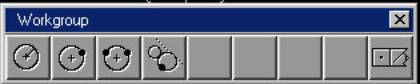
Click
on the Circle icon in the Geometry Palette.

The
Circle Palette will appear.
Select
the Radius and Center Point icon.

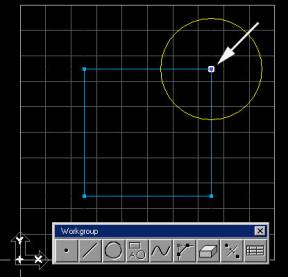
Select
the point in the upper right-hand corner of the square as shown. This will be the center point of the
circle. Enter 20 for the radius and
click on the Single Circle icon .
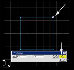
Your
screen should look like the following image.
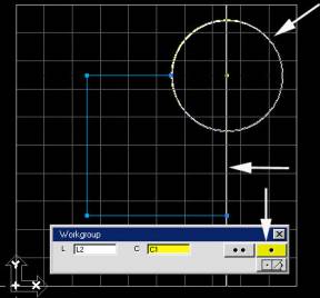
You
will now connect the circle to the square.
First, you must disconnect the point you used as the center point of the
circle.
Select
the point and click on the connect/disconnect icon in the Geometry Palette.
|
|
|

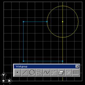
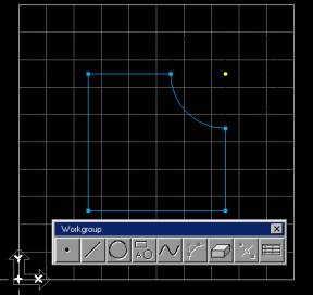
Your
screen should look like this.
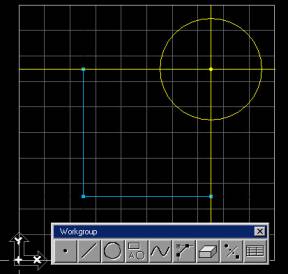
Notice
that the 2 lines joined by the corner point are now disconnected and have
turned yellow. You will now connect the
arc to the lines.
Select
the Point icon from the Geometry Palette.

Hold
down the control key and select the top horizontal line of the square and the
circle. Click on the single point icon.
The
system will find 2 points where the line intersects the circle. A dialog box will ask you which point you
want to connect. Select the point on
the left and click on OK.
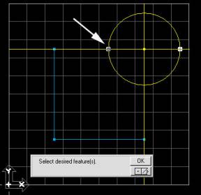
This
will trim the line and place a blue connector point between the line and the
circle.
Select
the Point icon from the Geometry Palette.

Hold
down the control key and select the vertical line and the circle as shown. Click on the Single Point icon.
The
system will find 2 points where the line intersects the circle. A dialog box will ask you which point you
want to connect. Select the bottom
point and click OK.
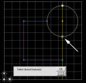
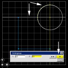
The
geometry trims and the arc is now fully connected. Your screen should look like this.
This
completes the exercise. Save the
file. Choose File-Save from the Main
Menu.