Exercise 8 - Workgroups
In this exercise you will create 2 layers of geometry for the same part file using Workgroups. Using Workgroups can help keep your geometry organized when you are working on a part file with multiple machining operations. Both the CAD tools and the Geometry Expert will be utilized in creating the geometry for this exercise.
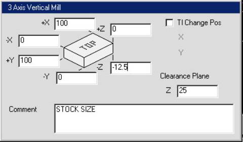
Create a new file named WORKGROUPS. Set the machine type to 3 axis vertical mill and the units to mm. Enter the values below for the stock size.
Select the Geometry icon from the Top Level Palette.

The
Geometry Palette will appear.
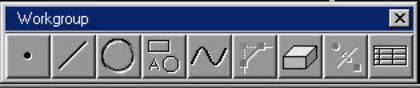
Select
the Shapes icon.

The
Shapes Palette will appear.
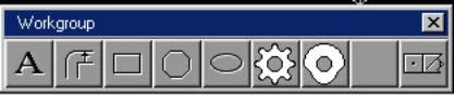
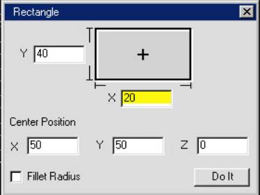
Select
the Box icon.

Enter
the values below and click on Do It.
You
will now add a midpoint to the top horizontal line. This will be used for the center point of an arc that you will
add to this profile.
Select
the point icon from the Geometry Palette.

The
Points Palette will appear.
Select
the Midpoint icon.

Select
the line as shown and click on the Single Point icon to create a midpoint on
that line.
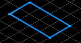
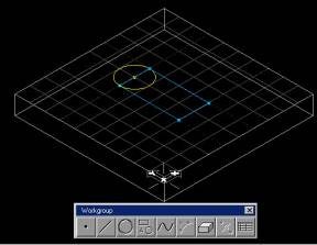
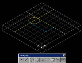
Your
screen should look like the following image.
Select
the Circle icon from the Geometry Palette.

The
Circle Palette will appear.
Select
the Point & Center point icon.

Select
the midpoint you created as the CP.
Select
the corner point as shown as the P.
Click on the Single Circle icon.
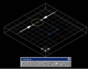
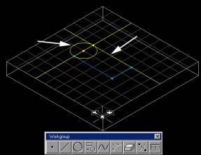
Your screen should look like the following image.
You
will now connect/trim the arc to the rectangle profile. Hold down the control key and select the 2
blue corner points as shown.
Select
the connect/disconnect icon to disconnect the connector points from the
profile.

Your
screen should look like the following image.
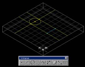
You will now connect the arc to the profile.
Select the circle and the yellow vertical line on the left as shown.
Select
the Connect icon.

A
blue connector point will be placed at the intersection of the line and the
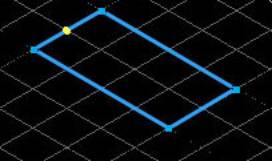
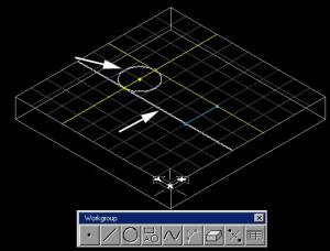
circle. Your screen should look like
the following image.
Hold
down the control key and select the circle and the other vertical yellow line
as shown.
Select
the Connect icon.

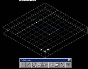
Your
screen should look like this.
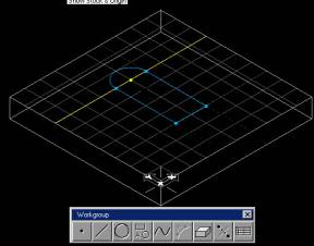
Note: If your arc is reversed from the image
above, select it and choose Modify-Reverse Arc from the Main Menu.
This
completes the profile on the first workgroup.
You will create a second workgroup that will contain geometry for 4
holes.
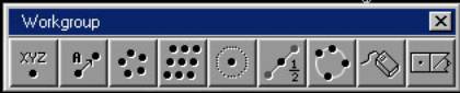
Single-click
on the Workgroups icon from the Top Level Palette.

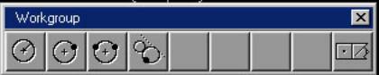
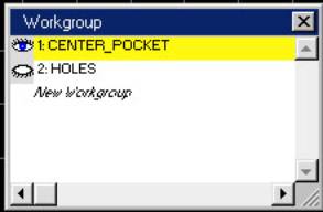
The
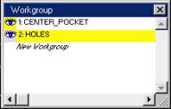
Workgroup dialog box will appear.
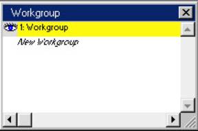
Select
New Workgroup to create a new workgroup.
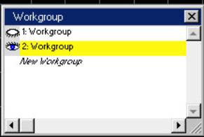
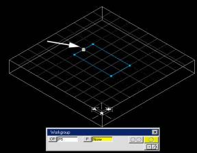
The
new workgroup is highlighted and now the active layer. The geometry you created should no longer be
on the screen. Change the name of the
new layer to HOLES. Double-click on the
second workgroup. In the Comment box
type in HOLES.
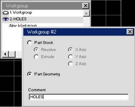
Click
on the X to close this dialog box and return to the Workgroup dialog box.
Next,
you will change the name of the first workgroup. Double-click on the first workgroup. Type in CENTER_POCKET in the Comment box.
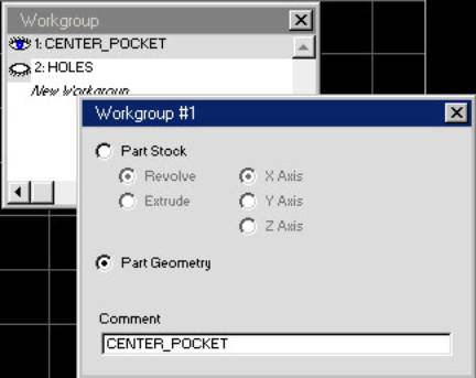
Click
on the X to close this dialog box and return to the Workgroup dialog box. Select the HOLES workgroup to make it active
and close the Workgroup dialog box.
You
will create 4 holes for this workgroup using the Geometry Expert.

Select
the Geometry Expert icon from the Geometry Palette

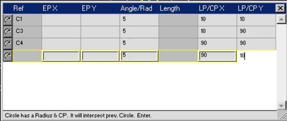
Enter
the following rows into the Geometry Expert spreadsheet.
Feature Type Ref. Radius CP X CP Y
Clockwise
Arc C1 5 10 10
Clockwise
Arc C2 5 10 90
Clockwise
Arc C3 5 90 90
Clockwise
Arc C4 5 90 10
The
Geometry Expert should look like this.
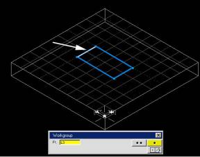
Hit
enter. Your screen should look like this.
To
view the first layer of geometry you created, select the Workgroup icon from
the Top Level Palette.

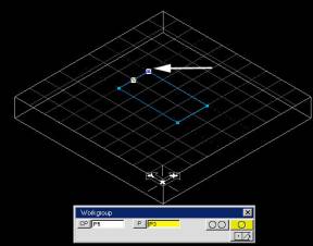
Select
the CENTER_POCKET workgroup and close the dialog box.
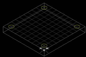
You
should now see the first layer of geometry you created.
You
can also view different workgroups at the same time. Select the Workgroups icon from the Top Level Palette.

The
Workgroups dialog box will appear.
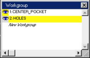
Hold
the shift key and double click on the eyes next to the names of the workgroups
to open them.
This
completes the exercise. Save the
file. Choose File-Save from the Main
Menu.